Mechanical Rigging - Dreadnought Animation Setup
When a modeler finishes creating a charter, it’s a static 3d mesh, like a marble sculpture. Before the model can be handed to the animator, it must be bound to a system of joints, bones and control handles. The process that takes a static mesh and prepares it for animation is called rigging. For humanoid models that usually use a skeleton system with inverse kinematics the process is less time consuming and quite straightforward. For mechanical rigging there are some aspects from a technical point of view that need extra attention.
In this case I choose a mechanical unit from the tabletop game Warhammer 40k, more precise the Dreadnought; It has a relative simple design but an interesting machine-driven system that can be rigged with nice results.
Before we start analyzing the model and creating the control system for the animations, we will discuss and explain the core rigging concepts and elements that will be used for our model and at the same time for any mechanical system ranging from a robotic arm to a car engine. I am using 3D Studio Max for creating the rigging but other CAD applications have the same or very similar systems for the rigging process.
The main systems are the following:
- Transform, rotate, position controllers
- Wire parameters
- Custom attributes
- Visual controls
Transform, rotate, position controllers
One of the most used controllers is the link constraint. Basically it creates a parent-child connection between elements from the scene. When the parent objects moves, rotates or scales, the child will copy the actions of the parent. This controller is very useful for creating the Meta links for a complex system.
A simple example will be the link between the chassis of a car and the wheels. The wheels will be linked to the chassis so it will move at the same time with the car. Of course the wheels will have an extra parameter that will rotate them proportional with the distance moved, but this is the “detail” rig.
Another very important component of the controller system is the look at constraint. This element controls the object orientation so that it will always look at other object or objects. Rigging the eyes of a character to look at a helper object is done with the help of this controller.
Wire parameters
Wire parameter lets us link parameters from two objects, so adjusting one parameter changes the other automatically. This can be one way or a two way connection that can create complex system of dependencies and of course animations. The basic parameters are the rotate, scale; move in one of the three axes but at the same time custom parameters, mathematical functions/expressions can be added.
Custom attributes
In many cases especially in complex animations we need to create custom controllers to easily manage and change different parameters of the animations. For this we can create custom attributes (float, percent, boolean and so on) that can control complex subsystem and/or link them together.
An important aspect is that all the custom attributes you create can be incorporated in the controllers or wire parameters creating more flexibility and a better final rig for the animator.
Visual controls
One of the most important aspects of the rigging process is to create a streamlined “interface” for the animator, so he can easily select and control the model and create good animation in the smallest time possible. For this we must “freeze” the components of the model so that no accidentally transformations would occur in the animation process. The next step is to create simple 3D shapes that act as helpers for different components or connections of the model. To keep to rigging as clean as possible, attribute holders can be created for the helpers so that different parameters can be accessed by just one helper. As we discuss the models structure, this aspect will be explained in more depth.
When creating mechanical characters, there are a set of good practices that will surely make your life a lot easier especially when you start the rigging process.
The first aspect involves the sketch, blueprint or real references used for guiding the modeling process. In many cases there are a lot of elements that look cool but are not suitable for animations. Analyze the subcomponents even try to model a simple version and rig them to see if you can incorporate them in the final model. Don’t start modeling complex objects for hours and then realize that the specific part cannot be incorporated into the rig.
The gold rule for creating good animations is that each component should have a practical purpose in the model. This aspect will help transmit a feeling of natural and familiar to the end-viewer despite the fact that the respective model could be something they never even dreamed of.
A very important rule when modeling complex objects is to apply at the end of the design process a Reset XForm modifier and adjust the pivot. The rotation, scale values and pivot points that don’t match the current shape need to be realign and reseted before rigging, otherwise it will be impossible to create proper links between objects.
Other good practices are:
- creating the symmetry of the components before the rigging process,
- good naming conventions,
- creating layers forbetter management of the scenes assets
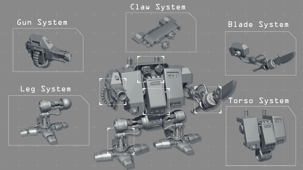
I divided the Dreadnought into five core components that correspond to the major 3D modules:
- Leg system
- Body system
- Grapple system
- Gun arm system
- Blade arm system
Each of the systems has their own control elements composed of visual 3d elements and attributes. These 3d elements have their position and rotation values frozen in the “idle” stance of the model and in case of problems with the animations you can always reset the transforms without needing to know the actual starting values.
The focus was on creating independent subsystems so that the animator can easily create complex sub animations that can then be integrated in the other systems.
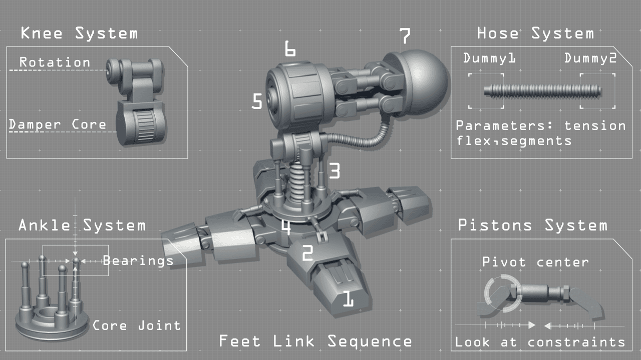
The legs of the dreadnought represent one of the crucial parts of the model. The mechanical structure resembles the human one, but in same aspects it has some new “features”. I structured the rigging process in two components: the micro elements and the macro ones.
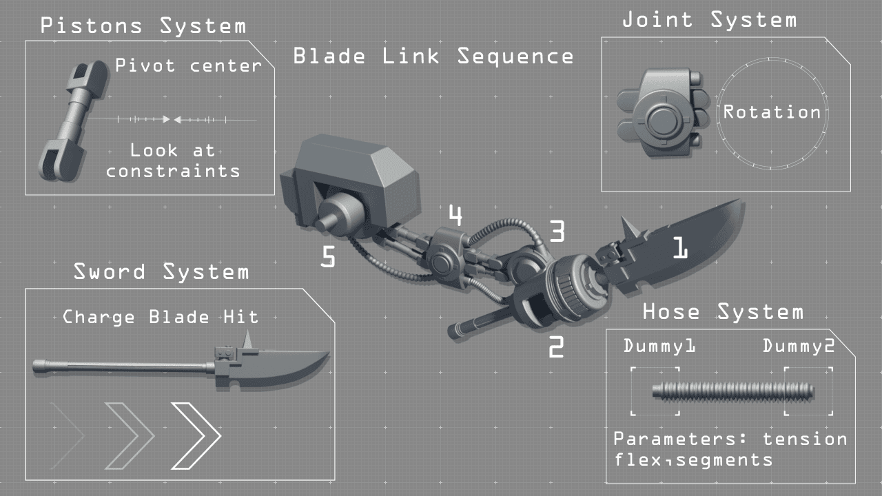
Basically the first part focuses in creating the detail rigging such as the pistons, finger rotations damper and hose. For the pistons I used look at constraints with the help of dummy objects linked to the pistons because we cannot have loop constraints for the pistons:
Piston_A > looks_at > Piston_B > looks_at > Dummy_A (Piston_A is linked to Dummy_A)
The damper and the hose are special 3DS Max objects that have a series of parameters like length, tension, drag and so on that depending on your model need to be customized to have the best simulation. At the same time I used dummies to connect the endings to the leg to have a more modular approach and to easily test without linking and unlinking from the main system.
Once the subsystems are in place I created some helpers (3d simple shapes) and I linked the elements to create the leg rig component. To help me control the fingers motion I created an attribute holder for the base foot where all the fingers rotations are linked to scroll bars that transpose values from -15 to 15 in rotation angles( due to the fact that 3DS uses radians is better to use the function DegToRad(value) for good results).
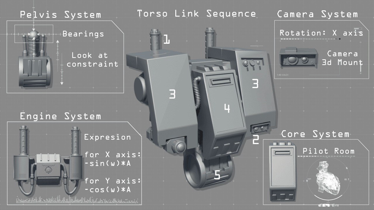
The torso/chest represents a large percent of the entire model but has a smaller amount of parts for rigging than the legs. The focus was to create a small amount of mobility to the torso without creating “weak” points (from an armor stand of point) in the design of the dreadnought.
The solution was to create a “pelvis” for connecting the legs and a system of pistons, bearings that would simulate in a small degree the spine movement. Another big component was the back engine system and exhaust.
I created a controller for the system with a speed value that can be changed by the animator. This value goes in two expressions that create a loop animation (an engine vibration). The function “sin(F*Speed*100)*0.25” creates a motion on the y axis with a pulse value of(F*Speed*100) and an amplitude of 0.25. The same function but with cos is used for the X axis of each exhaust system.
Another element is the camera system. It’s a simple model with a rotation rig but at the same time it has a render camera attached to it. It will be used for creating CGI animations for a unique point of view. Last but not least the pilot room (the core system) is the central piece of the dreadnought. It does not have any complex elements but in future development the interior will be fully modeled and rigged.
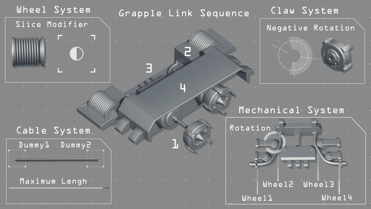
The grappling hooks can be viewed as a module to the torso component but due to its complex design and rigging, I made a standalone piece. The main components are the claws, rollers and the mechanical wheel system. All of these components are linked to the claw, more precise to the Y transform position. The interior mechanics of the claw rotate counterclockwise with a ratio of Y_distance/10. The cable is a 3dsmax hose that has one end linked to the base component and the other to the claw.
To generate the roller cable effect I used a slice modifier that acts like a mask hiding parts of the rolled cable as the claw moves. The plane of the modifier moves along the roller with a ratio… and a long side a rotation parameter it gives the desired effect.
For the mechanical wheels that act as the trains and retract the claws I used one way wire parameter setup. The two claws and their subsystem are independent, so each one can move different distances and speeds in distinct time intervals. The final step was to create a parent dummy object for the grappling system so I could link it to the main body without breaking the “detail” rig setup.
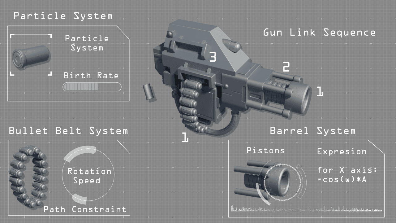
The gun of the dreadnought is a simple model and the rigging focuses on creating a fire cycle composed of the following sub rigs: barrel recoil, bullet belt rotation and the empty shell particle system. All the systems are interconnected to one custom attribute (shoot speed). The barrel recoil speed uses a simple expression cos(F*shoot_speed*100)*4 on the X position axis.
The bullet belt has a path constraint with a spline and each bullet follows the track with the speed given by the shoot_speed.
The last element is the empty shell particle system. This is a standard particle system with a shape instance propriety (to instantiate the 3d shell model), gravity, drag and wind space warps to better simulate the falling of the particles. I used a plane deflection for the collision and an age test to destroy the particles after a certain time. The emitting rate is controlled by the shoot_speed.
The blade rigging is very similar to the leg system. It’s composed of a set of joints that simulate the structure of the human arm with the help of the pistons. To give it a more organic feeling a set of hoses have been attached to the arm. The final component was the actual blade that has a custom attribute to better create the charge animation. The attribute range values (slider) are is linked to the Y transform axis of the blade.
This rigging solution is not the only one, another approach would be to create an IK bone structure and link the joints to them. Of course each solution has its pros and cons and the best solution is more oriented on the specific model you want to rig.
The rigging of the model is the core step in the process of animation and just one of the many needed for creating a CGI animation. The dreadnought is a relative straightforward example that utilizes many of the usual rigging tools available in most of CAT applications. Due to its simple model design is easy to create the connections between its mechanisms and to understand how it should work.
In the future there are two aspects that I would like to focus on further. The first one would be regarding creating a small CGI animation of the dreadnought and the pipeline used for it. The second would focus on hard surface modeling for production in 3DS Max. This will focus on smooth organic shapes for humanoid systems with a much higher model complexity and a different approach to the modeling process.
→ If you want to find out more about the author of the article click play on the below video.


