Environment Modeling for Mobile Games
My task was to create a 3d weapon selection screen for the mobile game Zelgor. It looked as a simple task, but once we analyzed to game flow especially between the GUI systems we realized that a more complex and natural interface was necessary. The response was to create a 3d command room (inspired from the 60s) that will host a set of functionalities and create a smooth and natural transition between different options in the scene.
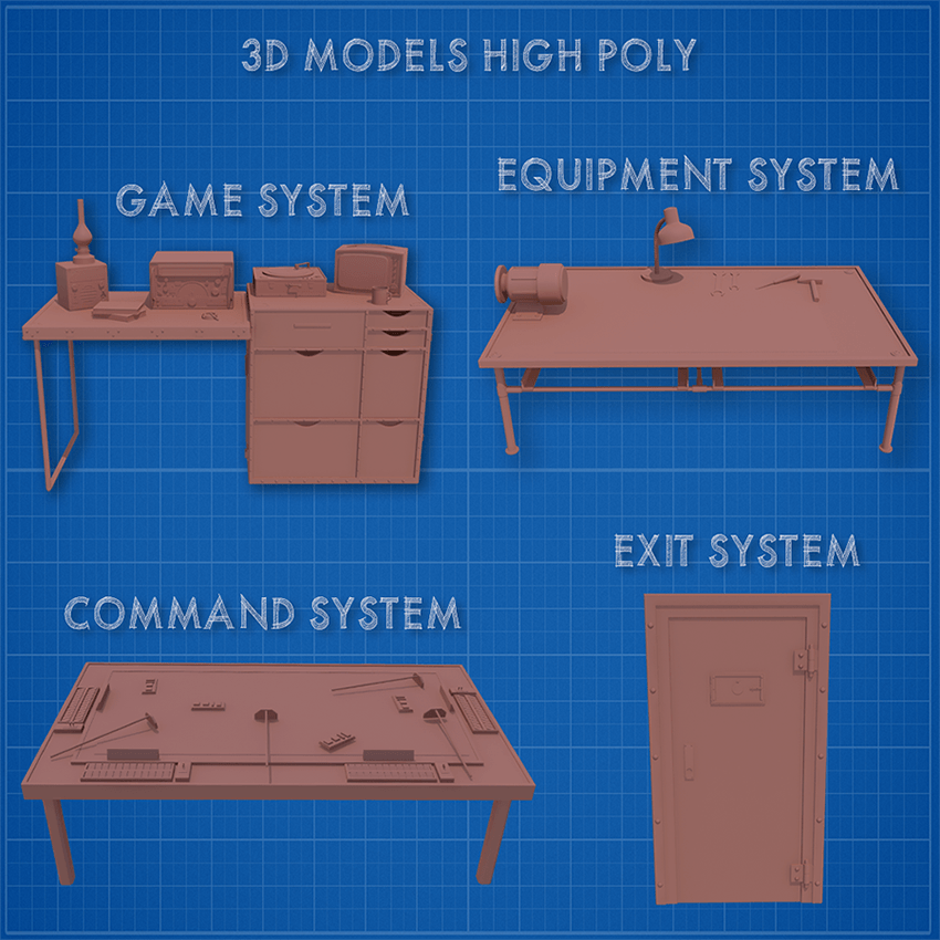
The structure of the room would consist of 4 core systems: equipment, game, command and exit. For each of these elements I created a list of 3d elements and the functionality of the environment.

Once the “blueprint” of the room was done, the next step consisted of researching actual pictures/footage and analyzing the elements that would be necessary for a command room. The main focus was to create an environment that would be functional and give a sense of shelter for the player.
In this presentation I'm not going in depths about hard surface modeling techniques in 3d studio, because in most part this topic was discussed in the article “The Pipeline Behind modeling, animating and integrating the Flak 88 AA Gun in Zelgor”. Still there are some key rules that will make your modeling process easier and more streamlined:
First rule is to create as many subcomponents as you need for each model in the scene. In other words, don’t try to use one mesh to create every detail because in most cases it will backfire badly.
A good modeling workflow is to use as much as you can NURBS modeling. NURBS, which stands for Non-Uniform Rational B-Splines, is an industry standard for designing and modeling surfaces. It is particularly suitable for modeling surfaces with complex curves with relative small amounts of polygons that can be tweaked on the fly.
Last but not least, try to reuse the high poly models for generating the low poly versions. For this you need to plan “smart” the high poly versions. Use swift loops, chamfer to create a base version that with turbo or nurbs smooth modifiers will generate the high poly elements. After that you clone the model, delete the extra loops and you have a low poly version ready to go.
The final step in the high poly modeling process is to add a diffuse color code for every subcomponent of the models. These colors will represent the materials used for texturing the low poly elements (wood, metal, glass, plastic and so on). This and the normal map will be the textures extracted from the high poly model to the low poly version.
The final step in the modeling process is to create the low poly version of the scene and extract for each element two maps: the color diffuse and most important the normal map. Of course, for this, each 3d object needs to have his UV unwrap done so that we can project the 3d details to a texture map.
Baking a RGB map from your high poly model is a huge time saver allowing you to quickly extract selection masks that you can use as the basis of your texture.
The normal mapping or "Dot3 bump mapping" is a technique used for faking lighting of bumps and dents and used to add more details to 3d models without using more polygons. Normal maps are commonly stored as regular RGB images where the RGB components correspond to the X, Y, and Z coordinates, respectively, of the surface normal.
To calculate the Lambertian (diffuse) lighting of a surface, the unit vector from the shading point to the light source is dotted with the unit vector normal to that surface, and the result is the intensity of the light on that surface. By using a 3-channel bitmap textured across the model, more detailed normal vector information can be encoded. This technique in correlation with advanced lighting system can create very realistic 3d effects and details on low poly models.

Physics based shaders require a set of textures that work together to achieve a realistic material that reacts natural to the light sources of the game engine. For this will need to create the following texture maps: diffuse, normal specular and gloss.
The diffuse map is your basic color texture; here you define the color information for your materials.
The normal map provides per pixel lighting/shading information. In our case, we generated the normal map from our high detail model, but at the same time, we can add further details with the help of Nvidia Normal Map, Crazybump,Bitmap2Material and other programs or plug-ins.
The specular map is used to define both the color and the strength of the specular reflection highlights.
The gloss map is used to define the “sharpness” or “roughness” of the specular reflection highlight, essentially how wide or narrow the highlight is. Darker gloss values are used to define matte materials, while brighter gloss values are used to define glossy materials.
When working on texturing is important to generate all the textures at the same time. You can use Photoshop, Mudbox and many other 2d/3d texturing applications to help you create the maps you need. It’s equally important to understand the physical properties of the materials in real life and how they react to each other and the lighting conditions.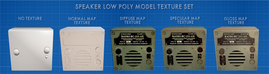
For the speaker we used 3 materials each with its unique physical characteristics: painted metal, rough plastic and brass.
Painted metal is a complex material composed of 4 layers. The first was the actual glossy paint (military green and, in our case, black ). The second layer was the scratches, marks, small dust particles, color desaturation that give it a worn-out aspect. The third layer focuses on deep edge corrosion and scratches that are more visible and show the actual metal underneath. The final layer was the information texts on the speaker.
The rough plastic is a relative easy to do material because it’s basically just flat colors. For the diffuse map I chose a dark grey color. I added a dull reflection and some scratches. The normal map did all the heavy lifting for the plastic components adding all the small details to the buttons.
Brass is all about diffuse and specular color. It’s one of those materials that are difficult to represent without full color specular maps (usually it’s recommended to have full color specular map, opposite to the gloss map that is only a black and white texture). You can add some patina effect for aged effect and use average values for the gloss texture.
Another family of materials that require a full spectrum specular is the lacquered and/or painted wood. The material can be easily seen in action on the old TV model in the scene. The diffuse map was a wood texture. The colored specular had the wood grain integrated because I wanted the reflection to come from the wood profile, not just from the glossy coating. As in the case of the speaker, some scratches, edge wear has been added to create a more natural feeling to the model.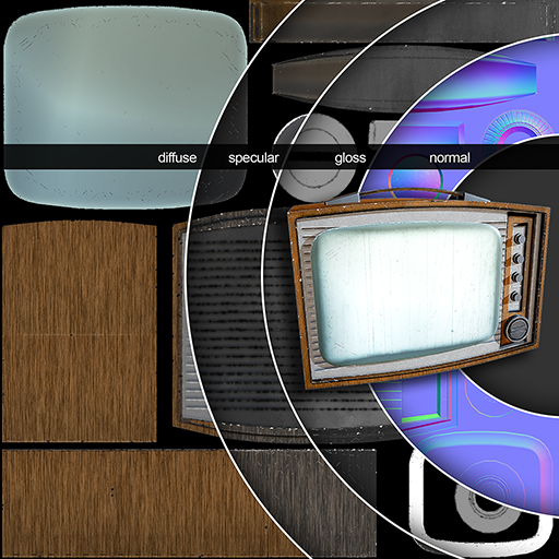
In the unity 4.x version there is no physical based shader out of the box. In the upcoming unity 5.0 this problem will be resolved with the “standard” shader that will help create physical based materials easily in any targeted platform.
For now we used third party plugins and shaders to create the materials. These materials have an extra texture slot for the specular map and the ability to change the values of the specular intensity and sharpness.
The gloss map can be added in the transparency channel of the specular map (just create a new channel in Photoshop and copy the gloss map there). The only downside is that for this to work you need the actual 32 bits image otherwise the map will not load. Due to this fact, for mobile gaming (all the textures are compressed) the gloss map cannot be added but can be simulated in some degree.
All this complex materials would have no impact without the help of Image Based Lighting. The lighting is done from HDR images that allow a high degree of realism.
HDR images can represent a greater range of luminance levels found in real-world scenes, from direct sunlight to faint nebula. It is often achieved by capturing and then combining different exposures of the same subject matter. In other words, when you render a 3d model the background of the scene is what gives the mood, tone and contrast of all the elements (fig7.0). The specular and gloss values of the image bellow have been overhauled to better visualize the different ambient lighting scenarios.

Once the IBL System has been added ( skyboxes), the next step is to add the light system from Unity. Image based lighting must be treated as ambient lighting; you still need directional lights to your scene for the sun and other light sources (spot, point, area) to light and cast shadows.
The final step is to bake the shadows into directional lightmaps, because real-time shadows are one of the most heavy resource eating elements on any platform. The directional lightmaps work exactly like the classic single Lightmap with one major addition: Static objects exhibit full lighting and specular / bump effects from all the light sources (Auto / Realtime-only / Bake-only).
To better visualize all these elements, I exported the weapon selection screen to the web platform so that you can walk around the scene and inspect each element freely. The controls for moving around are the following:
W-move forward, S-move backward, A-move left D-move right.
The mouse is used for camera rotation and pressing left mouse gives you a zoom in/out mode to better view the 3d models.
The roof of the room is hidden so you can see the skybox, and with the “R” key you can rotate the sky to see how it affects the specular and glossiness maps of the materials. The day/night illumination system can be activated by pressing the “+” and “– “ keys on your keyboard.
For this demo all parameters of the physical properties have been raised up to better see the visual differences. Note that this export is the raw project from iOS without any tweaks/optimizations for web development and that you need to install the unity web plug-in on your browser to view the content.
I hope this article helps new 3d designers to better understand how to achieve and, more important, what are the main steps behind creating game ready environment assets.
At the same time, physic based rendering is an exciting trend in real time rendering. The term is about many things (global illumination, image based lighting, physic based shaders, energy conservation and so on), but what makes it different from its predecessors is the more detailed and intuitive reasoning behind the behavior of light and surfaces.
The 3d designer must change the way he produces textures for its 3d assets because lots of the lighting information will be baked in the textures. To create realism, you may also want to adjust to what real materials are like, what specular ranges make sense, how different lighting conditions affect your models and so on. At the same time, due to the growing number of textures used per object, you may need to downgrade the resolution of the textures and optimize the unwrapping to squeeze as much detail as you can in each texture.
On the other side, all the real time global illumination data require a lot of computing power, so in most cases the developer must understand the hardware limitations and try to achieve a balance between baked and real-time global illuminations. Unity 5 comes with a new set of light baking features, new lighting workflow and a new “unified” shader system, that will help the developer to achieve his desired results within this new system.
This means that both, the developer and the artist, must understand the motivations behind these changes and how old means of producing digital art are changed in this new process.
→ If you want to find out more about the author of the article click play on the below video.